


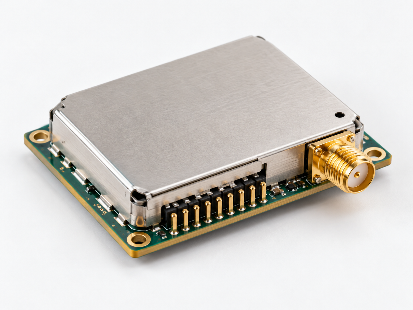
A GNSS timing module gives engineers a satellite-referenced time input that can be integrated into a controller, industrial gateway, event recorder or complete clock system. Yet two receivers with similar navigation specifications may behave differently in a timing application. What matters is not just how many satellites they see, but how accurately their pulse-per-second signal is generated, how they handle weak reception and how their output reaches the host processor. This guide compares five JCOM IoT receiver models and explains which specifications to prioritize when designing equipment for dependable timestamps. The broader case for synchronized infrastructure is covered in why time synchronization matters.
Explore the IoT timing modules range if you are developing equipment that needs a GNSS-referenced timing source.
How to Evaluate Precision Timing Modules for Synchronization
Six Parameters to Compare
To evaluate precision timing modules for synchronization, begin with the system requirement rather than a receiver’s headline channel count. Timing design is an end-to-end problem: the GNSS reference, local oscillator, firmware, electrical interface and distribution network all contribute to the timestamp seen by the application. Compare candidate modules using six criteria and document the conditions under which each value was measured.
- 1PPS time accuracy: the quoted uncertainty of a reference pulse under specified reception conditions, not general GPS position accuracy.
- Constellations and bands: which satellite signals are available, and whether the receiver operates on one band or a defined dual-band combination.
- Sensitivity and time to first fix: how quickly a usable solution appears and how robust tracking remains as reception changes.
- Host interfaces and protocols: electrical voltage, UART/I2C/SPI/USB/CAN options where available, messages and how the PPS edge is exposed.
- Power and environment: supply range, typical acquisition and tracking draw, temperature limits and behavior during outages.
- Antenna management: compatibility with the proposed active or passive antenna and whether a broken or shorted feed can be detected.
Specifications such as ‘ruggedized precision timing for industrial IoT’ also require checking the board’s enclosure, connectors, electromagnetic compatibility and thermal design; the receiver module rating does not certify the finished device. Engineers should include a prototype test with representative antenna placement and temperature conditions before committing to production.
PPS Accuracy: The Number That Matters for Timing
Position Accuracy vs Time Accuracy
One pulse per second, or 1PPS, is a recurring timing edge aligned to an absolute second when the receiver has a valid timing solution. The host processor can use it to discipline a local clock and assign precise times to captured events. Coordinate error is measured in metres; PPS timing error is measured in time units such as nanoseconds. Better navigation accuracy does not guarantee better timing than a simpler GNSS synchronization module.
For the JCOM IoT range, the ICB-230 lists a 10 ns time-accuracy specification, while the ICB-40153, ICB-40158 and ICB-88156 list 1PPS at 20 ns. The ICB-230 is consequently a useful reference when comparing stated pulse specifications, but values should never be treated as guaranteed system-level accuracy. Cable propagation delay, pulse capture circuitry, firmware scheduling, receiver lock state and antenna conditions can dominate the final result. A module’s 1PPS output also does not by itself make the host an NTP or PTP server.
Specify the required timing error at the actual event-recording point, then allocate an error budget to GNSS reception, internal processing and distribution. For SCADA applications, the acceptable error may differ greatly between trend logging and protection-related measurements. State how the system behaves during GNSS loss: an unsupported holdover claim is not a substitute for a measured oscillator specification and alarm strategy.
Constellations and Frequency Bands
Single-Band L1 or Dual-Band L1/L2/L5
Modern receivers can use GPS, GLONASS, Galileo, BeiDou and QZSS. Combining appropriate satellite constellations may help availability where the sky view is limited. Regional augmentation such as WAAS, EGNOS, GAGAN and MSAS is listed for the ICB-230 and ICB-88156; these services are primarily associated with navigation corrections rather than a guarantee of better PPS timing. A GPS timing module restricted to one constellation can still work in some systems, but a multi-constellation design often offers a wider choice of satellites for the receiver to track.
The dual-band ICB-40158 supports two alternative RF arrangements: L1+L2 or L1+L5. It should not be described as simultaneously receiving L1, L2 and L5 in one three-band configuration. Dual-frequency measurement can help mitigate ionospheric delay and improve robustness in difficult environments, although antenna quality and multipath still matter. By contrast, the ICB-40153 works with single-band signals including GPS/QZSS L1, GLONASS G1, Galileo E1 and BeiDou B1I. Comparing bands is useful only if the intended antenna and firmware support the chosen mode.
Comparison of JCOM IoT GNSS Receiver Modules
| Model | Channels | Constellations / bands | 1PPS | Interfaces | Selected feature |
|---|---|---|---|---|---|
| ICB-230 | 230 | GPS, GLONASS, Galileo, BeiDou, QZSS, SBAS; L1 | 10 ns | UART (3.3 V TTL) | Up to 25 Hz; A-GPS |
| ICB-210GR | 88 | — | — | — | 22.1 mA tracking; hot start <1 s |
| ICB-40153 | 40 | GPS/QZSS L1; GLONASS G1; Galileo E1; BDS B1I | 20 ns | UART, I2C, SPI, USB | Single-band RTK |
| ICB-40158 | 40 | L1+L2 OR L1+L5; multi-GNSS | 20 ns | UART, I2C, SPI, USB, CAN | Dual-band; antenna monitoring |
| ICB-88156 | 88 | GPS/QZSS, GLONASS, Galileo, BDS, SBAS; L1 | 20 ns | UART | 15 mA GPS/QZSS; antenna monitoring |
A dash indicates a field intentionally left unspecified in this comparison; do not infer an interface or timing accuracy from the receiver’s navigation capabilities. Figures describe individual modules, not the timing performance of a finished SCADA or telecom system.
Sensitivity, Time to First Fix and Antenna Monitoring
Why Antenna Fault Detection Matters on Unattended Sites
Cold-start sensitivity, tracking sensitivity and time to first fix (TTFF) describe different phases of reception. A module that can continue tracking a weak signal may still need a clear sky view and more time to obtain its initial solution after complete power loss. JCOM IoT lists a 29-second cold start and one-second hot start for ICB-230; the ICB-40153 lists 28 seconds and one second, and the ICB-40158 lists 24 seconds and one second. These are product specifications under test conditions, not promises for indoor cabinets or shielded installations.
GNSS reception depends heavily on the antenna, cable route and local environment. Metalwork, nearby transmitters, roof obstructions and poorly selected coaxial runs can degrade otherwise capable equipment. Active antennas need the correct bias arrangement; passive antennas demand an appropriate RF front end and cable loss budget. The ICB-40158 and ICB-88156 list short-circuit protection and open-circuit detection for antennas, useful features at remote sites where physical inspection is expensive. JCOM IoT also offers GNSS antennas and lightning protection for wider installation planning.
Antenna monitoring does not eliminate the need for software alarms. Log loss of fix, invalid time, receiver restart and suspected cable faults as separate conditions. For a rooftop installation, consider surge protection, suitable grounding and inspection access. In a control system, it is important to know not merely whether the receiver is powered, but whether its timing information can still be trusted.
Interfaces, Protocols and Power
Low-Power Designs for Battery Devices
After choosing a timing target, inspect how the host can read the module. The ICB-230 uses a 3.3 V TTL serial interface and NMEA 0183 messages. The ICB-40153 supports UART, I2C, SPI and USB; the ICB-40158 additionally lists CAN. The ICB-88156 specifies UART, and its antenna version must be selected appropriately. NMEA messages convey time and position information, but software must correlate messages with the relevant PPS edge and handle startup, rollover and invalid-fix states carefully.
Power planning should distinguish acquisition, tracking and standby states. The ICB-88156 specifies 15 mA in GPS/QZSS tracking at 3.3 V for the stated mode; the ICB-40153 lists 32 mA in L1 operation and the ICB-40158 lists 34 mA in either of its dual-band modes. The ICB-230 lists higher capture and tracking current figures. In battery-powered gateways, these differences affect runtime, but receiver power is only part of the budget: antenna bias, processors, radios, storage and regulator losses may outweigh it.
Precision Timing for SCADA, Telecom and Power Utilities
Module or Complete Time Server?
Precision timing for SCADA often begins with a trustworthy timestamp attached to a measurement or event. In a substation or industrial network, equipment may need to correlate alarms from multiple controllers, record a sequence of events or coordinate measurements with a common reference. Telecom systems use reference clocks for network equipment, while power utilities may have tighter requirements for protection and measurement applications. Architecture should reflect accuracy and resilience needs.
A time signal receiver module is one building block, not an entire synchronization appliance. It receives satellite signals and presents time information to an embedded host. A complete server also includes clock management, suitable holdover capability when specified, network interfaces, security, monitoring and protocol services such as NTP or PTP. For teams that prefer a finished device, compare exact time servers and read how to choose an NTP time server before selecting the deployment model.
Frequently Asked Questions
How do I evaluate precision timing modules for synchronization?
Compare the PPS accuracy specification, supported GNSS signals, TTFF and sensitivity, host interfaces, power draw and antenna fault monitoring. Then test a prototype under the antenna, enclosure and temperature conditions expected in production. The most useful comparison is the timestamp accuracy reached by the entire device, not a navigation specification taken in isolation.
What PPS accuracy do I need for SCADA and telecom equipment?
That depends on the application. General event logging may tolerate much greater error than particular telecom synchronization or power-system functions. Set a numeric requirement at the equipment interface, considering signal distribution and oscillator performance, before choosing a receiver. A module’s 10 ns or 20 ns PPS specification alone cannot establish the accuracy of a complete network.
Do I need a dual-band GNSS timing module?
Dual-band capability is useful when ionospheric effects, the chosen reference architecture or difficult reception justify the added complexity. It is not automatically necessary for every industrial clock. Consider sky visibility, antenna design, timing target and budget. The ICB-40158 offers L1+L2 or L1+L5 arrangements, so select and verify the appropriate RF setting for the project.
Which interface should a timing module have for an industrial controller?
Start with the electrical and software interfaces already supported by the controller. UART may be adequate for time messages, while other designs require I2C, SPI, USB or CAN as listed for specific modules. Check voltage levels, protocol framing and access to the PPS signal. Make sure software can identify invalid time and relate the PPS edge to the correct second.
Can a GNSS timing module replace a time server?
Not on its own. A receiver supplies a time reference to a host, while a complete server manages its clock and distributes time using network services such as NTP or PTP. If the project needs centralized synchronization with monitoring and network interfaces, evaluate dedicated exact time servers instead of assuming a bare GNSS module provides those functions.